Power Bank Coupler

High performance linearization system provides coupling without losses

Block diagram of a powerbank
© Fraunhofer IIS/Christopher Laske
Block diagram of a powerbank

The power bank coupler by Fraunhofer IIS makes the parallel amplification of signals and multi-carrier linearization along with loss-free coupling possible. The signal coupling process is used when multiple signals are to be transmitted over one antenna. This is advantageous in various applications such as on ships where there is only one transmitting antenna for sending multiple, frequency-agile shortwave signals. Applications in the area of public safety benefit in particular from this efficient, reliable coupling process.
Multi-stage linearization combined with digital predistortion

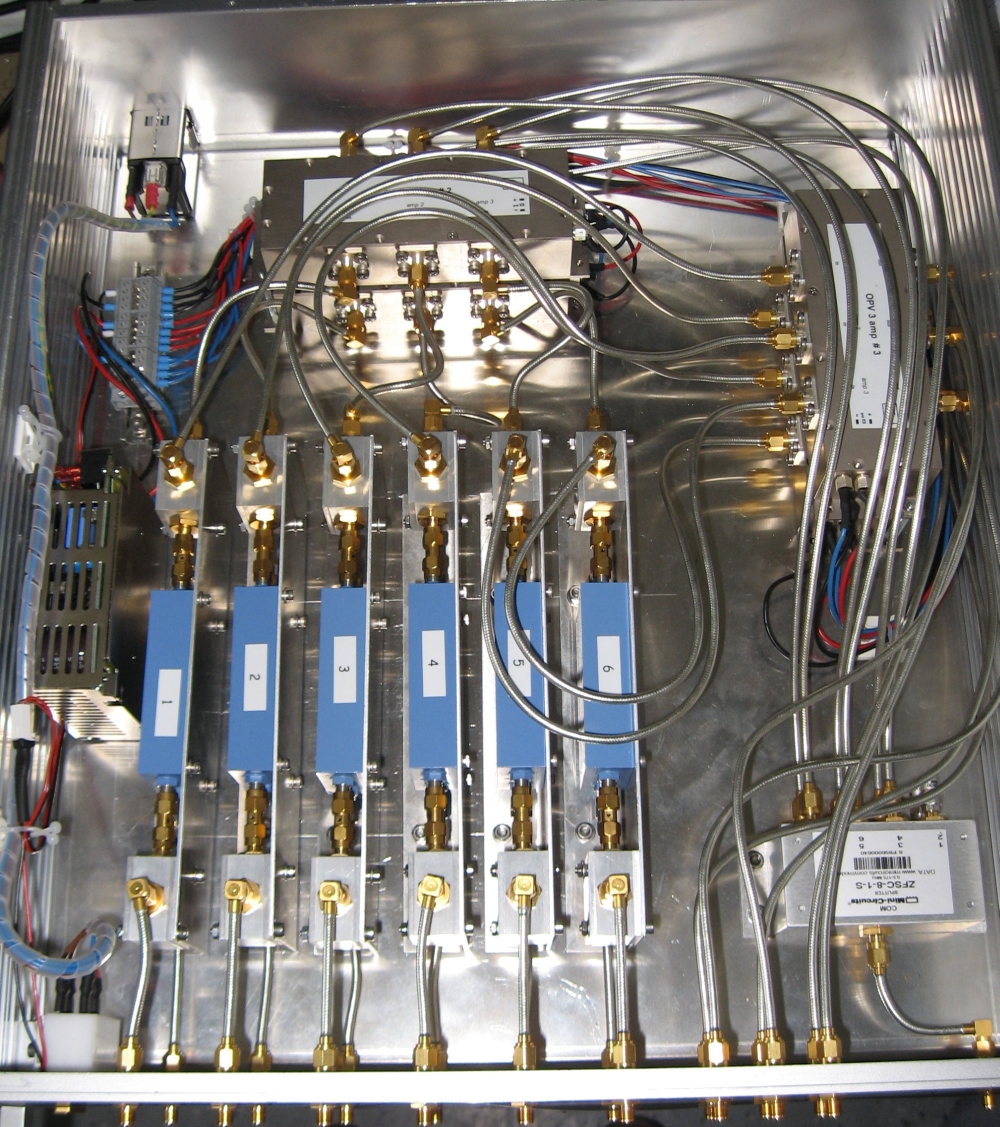
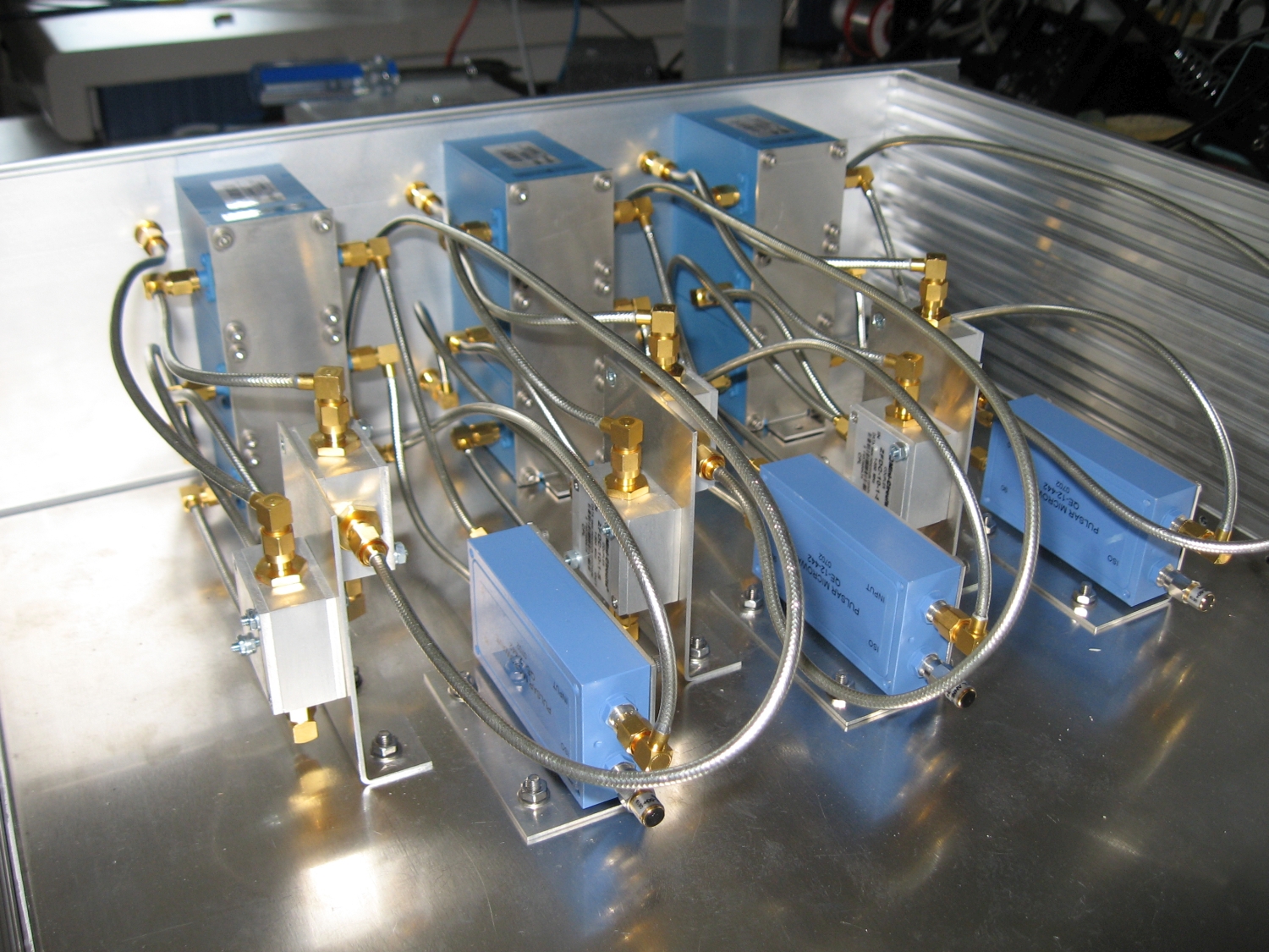
Interior view of the chassis of the power bank coupler demonstrator
© Fraunhofer IIS/Christopher Laske
The chassis of the power bank coupler demonstrator can align the amplitude and the phase

Without the power bank, each signal is amplified individually, so they have to be recombined after final amplification. With broadband coupling, this process results in high losses which can be avoided with a power bank. A power bank consists of power amplifiers that simultaneously intensify several signals at different frequencies and then transmit them using a single antenna. This requires high linearity to prevent from intermodulation of individual signals.

A special feature of the power bank coupler developed by Fraunhofer IIS is multi-stage linearization with digital predistortion, an innovative digital and analog feedforward loop. Together, these suppress the auxiliary lines to more than 90 dBc with no limitation on the selection of frequency for individual transmission signals.

Basic features of the power bank coupler

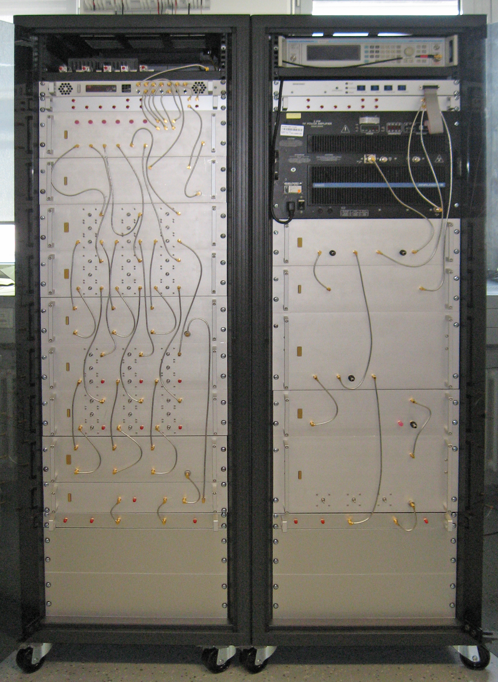
Demonstrator of the Power Bank Coupler
© Fraunhofer IIS/Christopher Laske
Demonstrator of the Power Bank Coupler
  • Frequency range: 1.5 MHz - 30 MHz
  • Up to 6 frequency-agile input signals
  • Multi-stage digital and analog linearization
  • Final signal-to-noise ratio better than 90 dBc (intermodulation, spurious, harmonics)

The integrated, digital feedforward linearization system has been patented by Fraunhofer IIS and can be adapted for the respective application based on customer requirements. For example, the system has been successfully adjusted to the UHF frequency range of 225 MHz - 400 MHz. Based on extensive experience in the area of antenna and radio technology, we develop new, customer-specific solutions or provide neutral assessment, optimization and expansion of existing customer concepts and approaches.

You may also be interested in


Linearization methods

Public safety

Go back to business area
“Public safety“