Inverse deflectometry – Defect detection on specular surfaces

What is deflectometry?

© Fraunhofer IIS
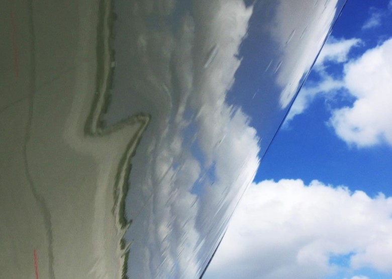
FIgure 1: Deflectometry reveals the topography of an object’s surface on the basis of distortions in the image reflected by it. This process is analogous to how dents in an aircraft hull can be seen in reflections of clouds.

The term deflectometry refers to a series of techniques for measuring and inspecting specular or partially specular surfaces. All of these techniques involve analyzing the reflection of a known pattern on the surface to be inspected. Accordingly, deflectometry techniques have a considerable affinity with human vision. People also perceive defects in specular surfaces on the basis of distortions in the reflected image. For example, dents in an aircraft’s outer skin are visible in reflections of clouds (see Figure 1). 

What are the benefits of inverse deflectometry compared to conventional deflectometry?

Inverse deflectometry is a technique developed at and patented by the Fraunhofer IIS that is particularly suited to industrial applications.
Inverse deflectometry is a scanning procedure, meaning that the object to be inspected is imaged in motion (alternatively, the sensor head can be moved instead).

Given that in industrial manufacturing the test object often travels along an assembly line, implementation of the procedure is straightforward. In many cases, it also permits considerable time savings, as under optimal conditions no additional measurement time is required.
Another major benefit of this procedure is that it can be used to capture transparent objects such as optical glass. This is a problem for conventional deflectometry, in view of the additional reflection that occurs on the reverse of the object. The resulting superimposition of two complex reflections cannot be easily separated. Therefore, in conventional deflectometry the reverse of the object must be dulled and blackened to suppress the reflection on this side. This makes the test object unusable for the end consumer, with the result that serial inspection of objects of this sort is not possible using conventional deflectometry.

Inverse deflectometry, on the other hand, allows comprehensive production-line testing of these objects for the first time. Under ideal conditions, this feature of inverse deflectometry can be exploited further. For example, the surface of safety goggles can be inspected on both sides at once by evaluating the signal reflected by each surface.
In this way, defects such as scratches, cracks, lacquer runs or inclusions on both sides of a pair of safety or sports goggles can be detected with a single measurement.
© Fraunhofer IIS
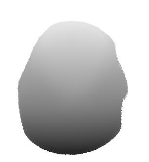
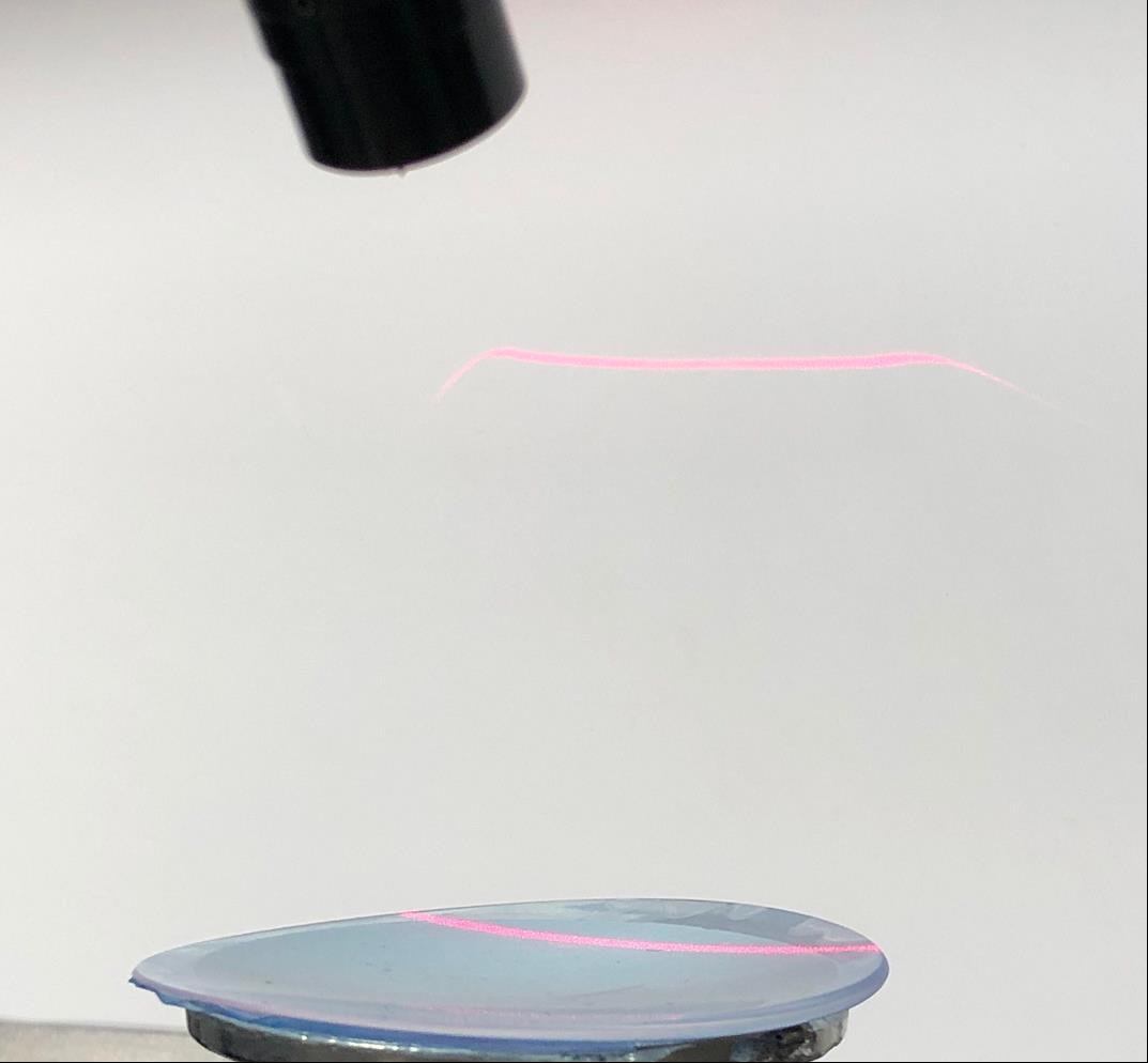
Figure 2: Measuring a varifocal lens using inverse deflectometry. As there is no need to dull or blacken the lens, it remains fit for use.
© Fraunhofer IIS
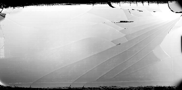
Figure 3: The resulting measurement data clearly reveal any defects in the component’s surface topography.
© Fraunhofer IIS
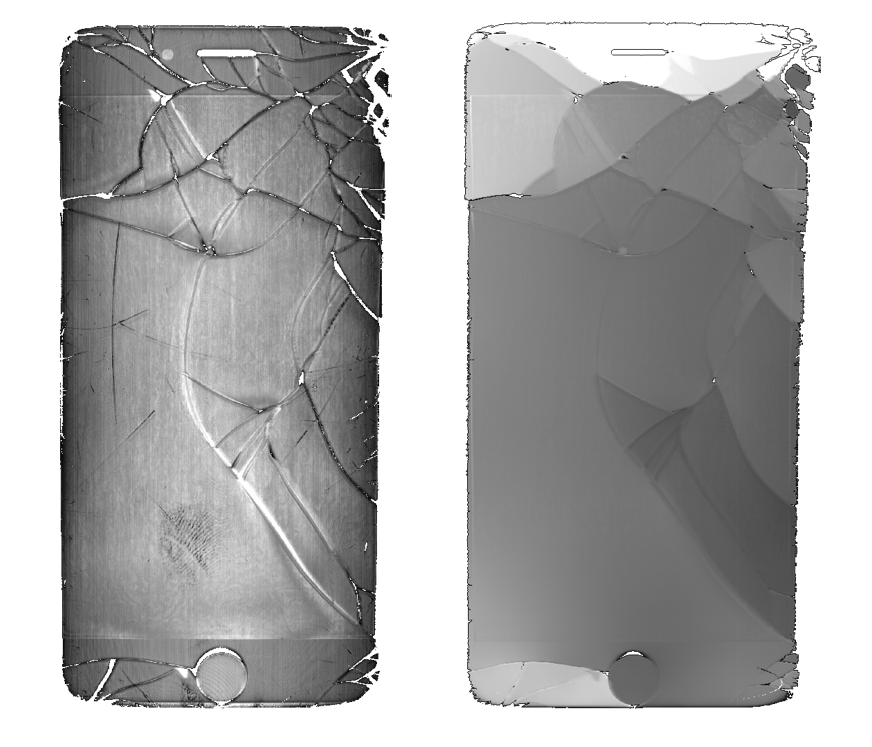
Figure 4: Defect recognition on a specular surface

What distinguishes deflectometry from the light section method?

The light section method differs from deflectometry in that it is used to inspect diffusely reflecting surfaces. Accordingly, inverse deflectometry is an ideal complement to the existing light section method, as it does not require the presence of a diffusely reflecting surface. The two techniques can also be combined to image surfaces that are both specular and diffusely reflecting.

Potential applications

© Fraunhofer IIS
Surface topography of a mobile phone display

Inverse deflectometry lends itself to measuring and detecting defects in (partially) specular surfaces.
Potential applications include quality evaluations in the following areas in particular:

Quality control and defect detection for

  • optical glass
  • spectacle lenses, particularly varifocals
  • spheres, e.g., ball bearings
  • safety goggles
  • headlight lenses
  • mirrors
  • windows
  • displays
  • injection molds
  • medical technology products
  • lacquered surfaces
  • flatness control for foils
  •  …  

What does a measurement setup for inverse deflectometry look like?

© Fraunhofer IIS
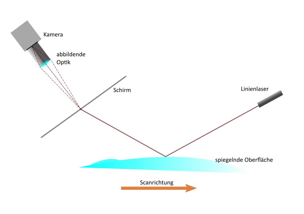
Measurement setup for inverse deflectometry

The adjacent figure shows a possible measurement setup for inverse deflectometry:  A line laser is projected onto the surface to be inspected. The specular surface reflects the light onto a screen, where it is captured by a camera.

In order to scan the entire surface, either the sensor or the surface must be moved in a linear path. In this process, the position and the surface normal at the point of reflection influence the projection on the screen. Determining the line’s path on the screen allows conclusions to be drawn about the shape of the surface under examination.
As with conventional deflectometry, the technique is particularly sensitive to local changes in angle.

Which other technologies might be of interest for you?


Visual 3D measuring technique

For the fast three-dimensional acquisition of surfaces Fraunhofer EZRT is mainly employing light-section techniques. This technique is very advantageous for moving objects.